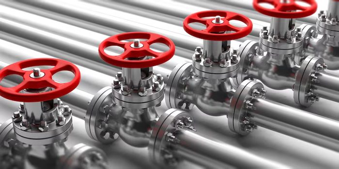
Pneumatic Valves
Solenoid, manual, check, flow-control and manifold valves.
Also searched as: solenoid valve5/2 valveair valveflow controlmanifold
-
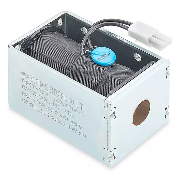
Solenoid Assembly for Polypropylene Strapping Machine
Voltage: 110 V
-
-
About pneumatic valves
Pneumatic valves regulate the flow and pressure of compressed air within a system, controlling actuators, cylinders, and other pneumatic components. Key types include solenoid valves, which use an electrical signal to actuate a spool or poppet; manual valves, operated by levers, pushbuttons, or rotary mechanisms; check valves, which permit flow in one direction only; and flow-control valves, designed to meter the rate of air flow. Manifold valves consolidate multiple valve functions into a single block, simplifying plumbing and reducing space requirements. Selection criteria typically involve port size (e.g., 1/8 NPT, G1/4), operating pressure range (e.g., 0.15 to 1.0 MPa), flow rate (e.g., Cv factor or L/min), and actuation method (e.g., 24V DC solenoid, detented lever). Spool configurations are often designated by the number of ways and positions (e.g., 5/2-way, 3/2-way normally closed). Common body materials include aluminum, brass, and engineering plastics, with seals typically made from NBR, FKM, or EPDM, chosen based on operating temperature and media compatibility.
How to choose
Choosing a pneumatic valve starts with defining its function: isolation, directional control, flow regulation, or pressure control. For directional control, determine the required number of ways (e.g., 2-way for on/off, 3-way for single-acting cylinders, 5-way for double-acting) and positions (e.g., 2-position, 3-position center closed). Next, specify the actuation method: electric (solenoid), manual, or pneumatic pilot. Consider the required flow rate (Cv value) and operating pressure range to ensure adequate performance. Finally, select the appropriate port size and thread type (e.g., NPT, G-thread) for system integration, balancing flow capacity with physical constraints.