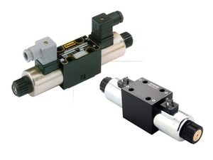
Hydraulic Valves
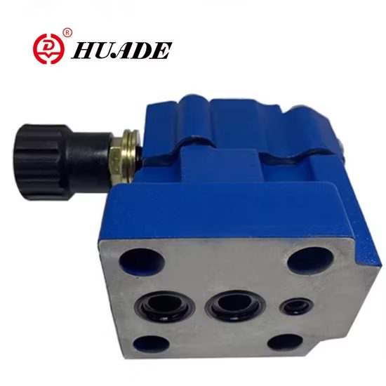
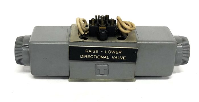
Directional, relief, check, proportional and cartridge valves.
Also searched as: directional valverelief valvecartridge valveproportional valve
-
-
-
-
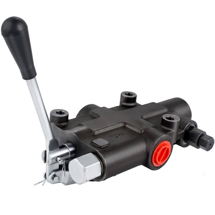
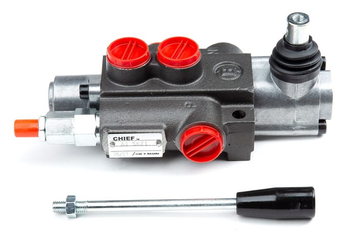
1 Spool 21 GPM Hydraulic Directional Control Valve
Flow Rate: 21 GPMNumber of Spools: 1Port Size: #8 SAE O-ring
-
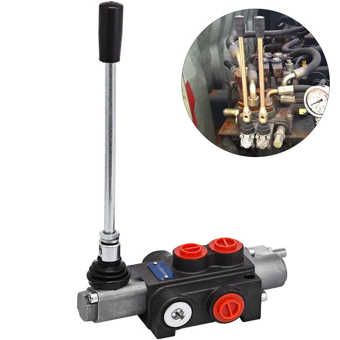
1 Spool Hydraulic Directional Control Valve
Number of Spools: 1
-
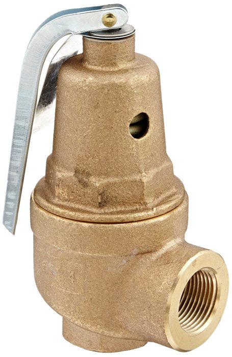
1" Bronze Boiler Pressure Relief Valve, 100 psi, Threaded
Set Pressure: 100 psiSize: 1"
-
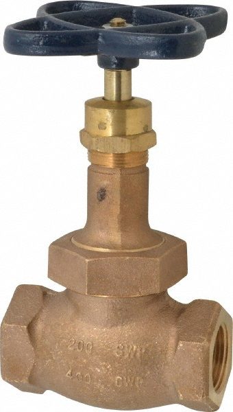
1" FIPT 200 psi (CWP) 125 psi (WSP) Bronze Threaded Globe Valve
Bore: 1"Connection Type: FIPTPressure (CWP): 200 psiPressure (WSP): 125 psi
-
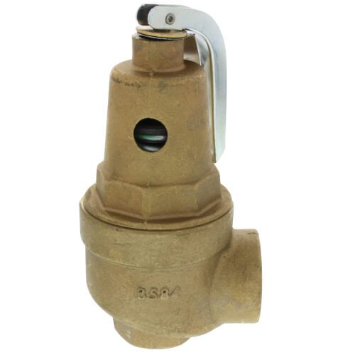
1" FNPT Bronze 75 - 125 psi Relief Valve
Set Pressure: 75 - 125 psiSize: 1" FNPT
-
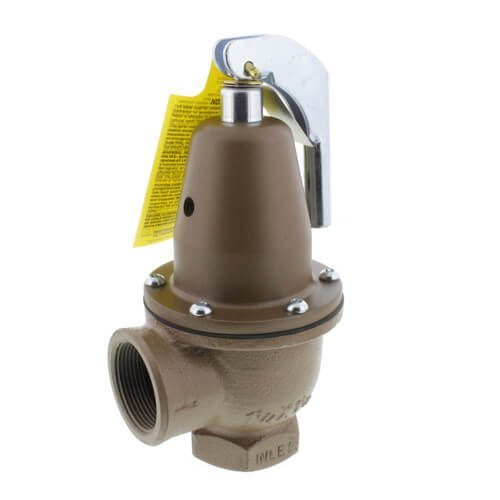
1-1/4" Iron Boiler Pressure Relief Valve, 30 psi, Expanded Outlets
Set Pressure: 30 psiSize: 1-1/4"
-
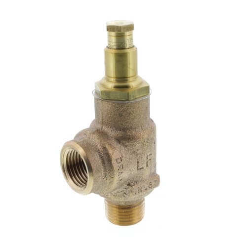
1/2" Pressure Relief Valve, Set At 125 psi
Set Pressure: 125 psiSize: 1/2"
-
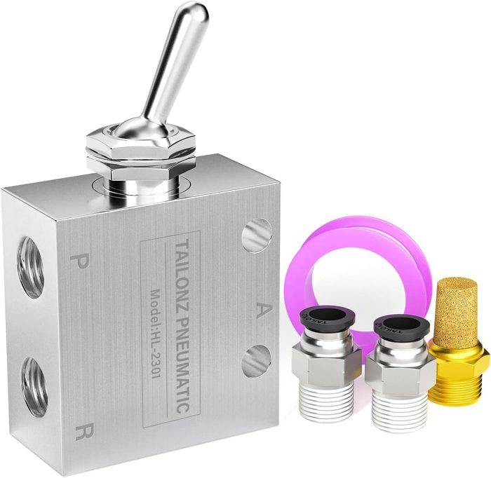
1/8" NPTF x 107mmL Aluminum 2-Position Normally Directional Control Pneumatic Valve
Length: 107mmMount Type: In-line or ManifoldSeries: 01VSize: 1/8" NPTFStyle: 2-Position
-
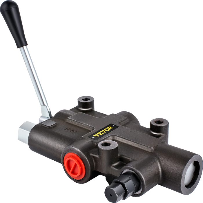
10" Port 3500 psi Steel 45°s Directional Control Valve
Port Size: 10"Pressure: 3500 psi
-
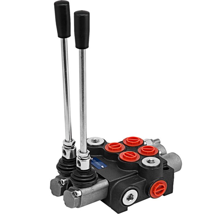
2 Spool Double Acting Hydraulic Directional Control Valve
Action: Double ActingNumber of Spools: 2
-
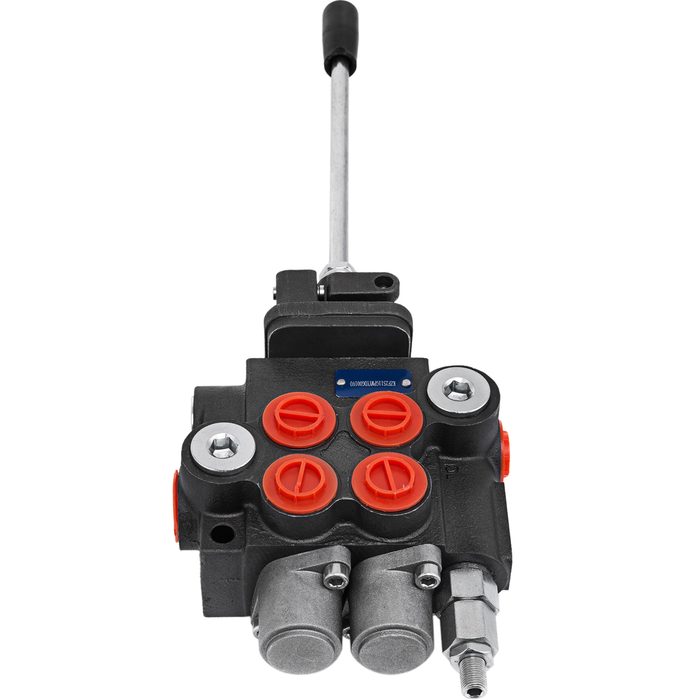
-
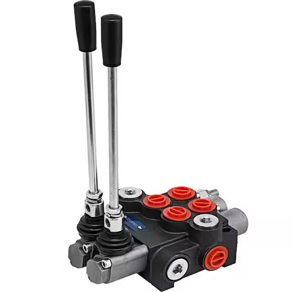
2 Spool Hydraulic Directional Control Valve, Open Center
Number of Spools: 2
-
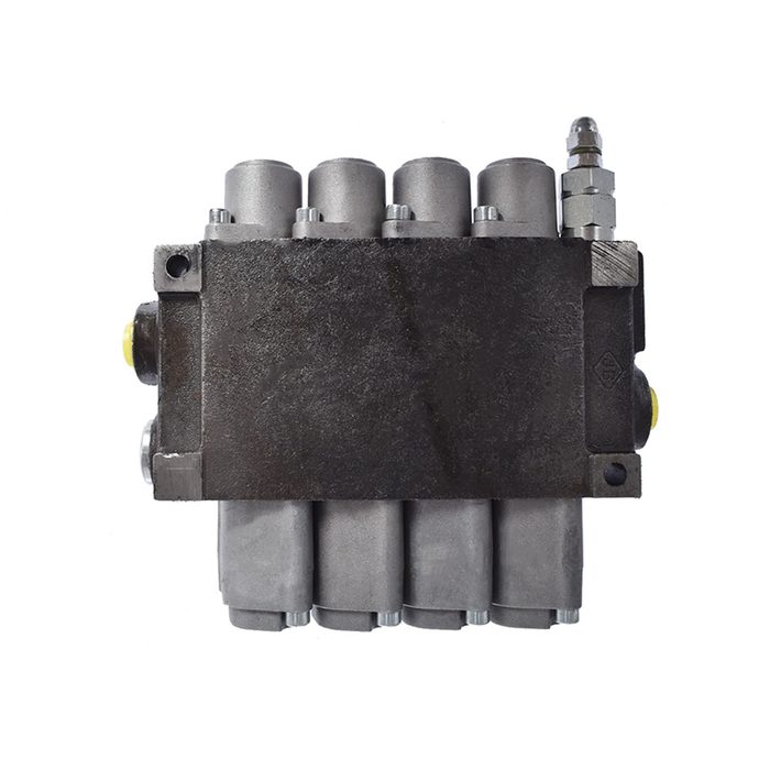
2 Spool Hydraulic Valve
Flow Rate: 21 GPMPressure: 3625 PSISpools: 2
-
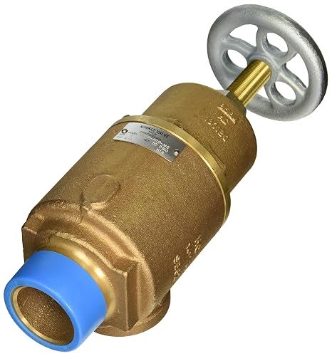
2" Inlet 2" Outlet Male NPT x Female NPT Safety Relief Valve
Inlet: 2" Male NPTOutlet: 2" Female NPTWorking Pressure: 250 psi
-
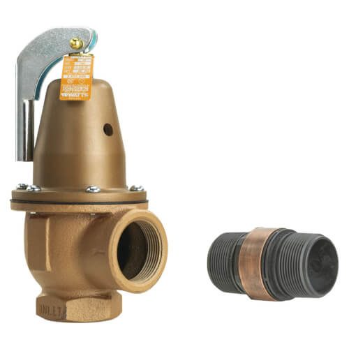
2" Iron Boiler Pressure Relief Valve, 40 psi, Expanded Outlets
Set Pressure: 40 psiSize: 2"
-
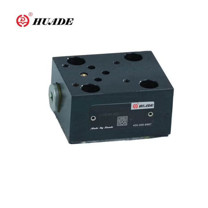
-
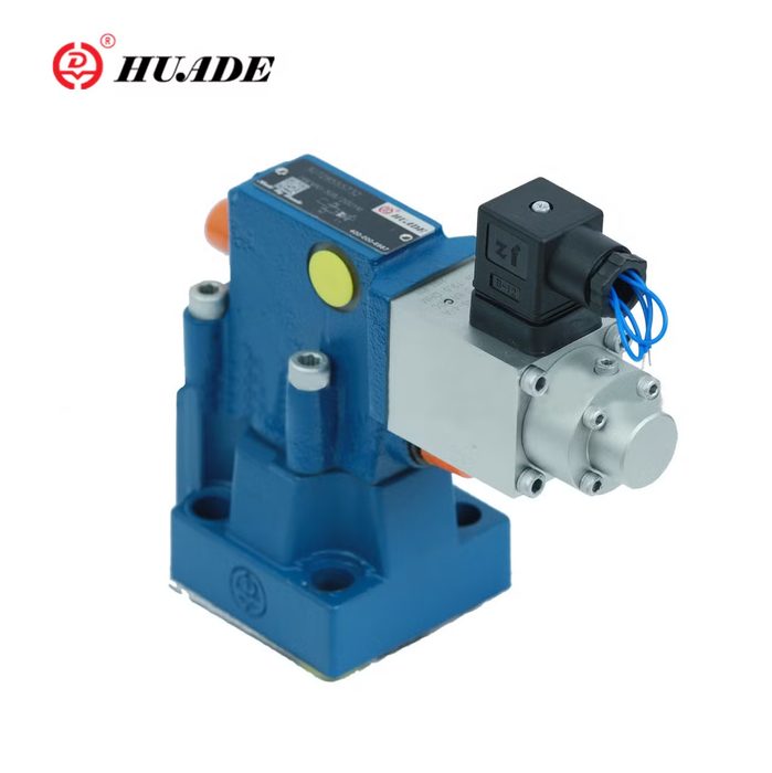
-
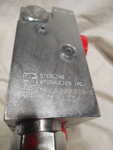
2/2 NC. Cartridge Valve
Configuration: 2/2 NC
-
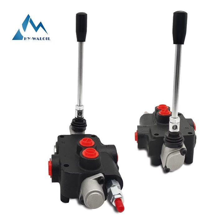
21 GPM 2-Spool Hydraulic Directional Control Monoblock Valve
Flow Rate: 21 GPMNumber of Spools: 2
-
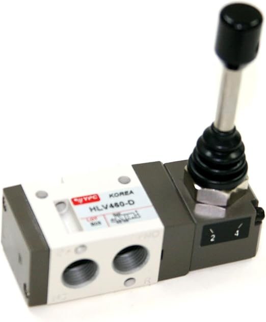
3 Port 2 Position Air Directional Control Valve
Max. Pressure: 150 PSINPT: 1/4"Ports: 3Positions: 2
-
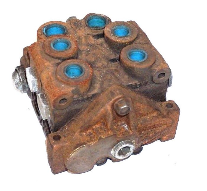
3-WAY DIRECTIONAL VALVE
Way: 3-WAY
from $400.00eBay $400.00 -
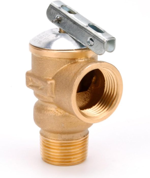
-
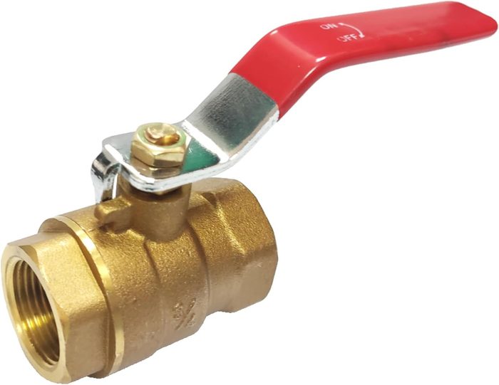
3/4" F-NPTxF-NPT 600 psi Forged Brass Ball Valve
Bore: 3/4"Connection Type: F-NPTxF-NPTPressure: 600 psi
-
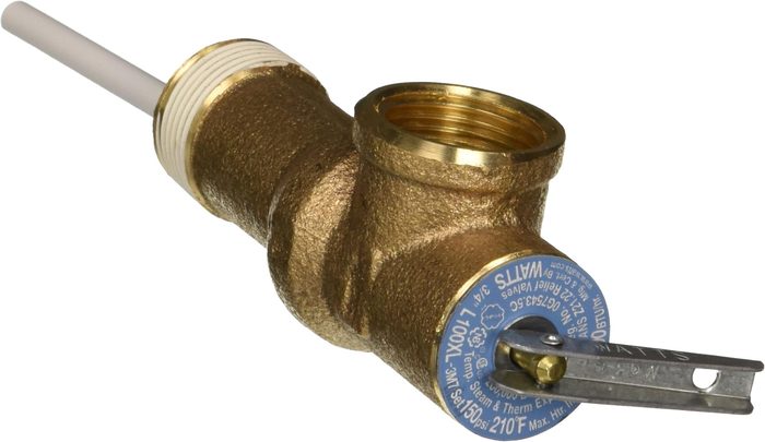
3/4" Temperature and Pressure Relief Valve
Inlet Type: MNPTOutlet: 3/4"Pressure: 150 psi
-
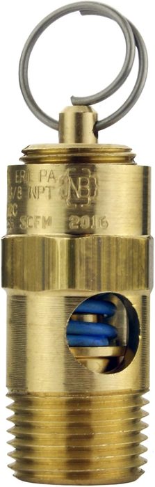
3/8" ASME Brass Safety Relief Valve 150 PSI
Relief Pressure: 150 PSISize: 3/8"
-
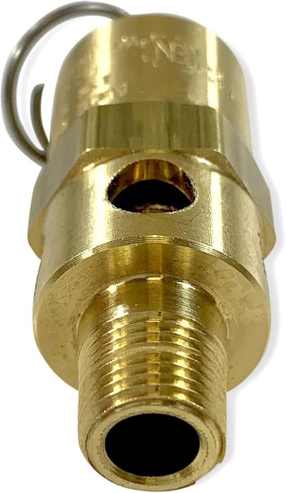
3/8-18 Steel Pressure Relief Valve
Size: 3/8-18Working Pressure: 10000 psi
-
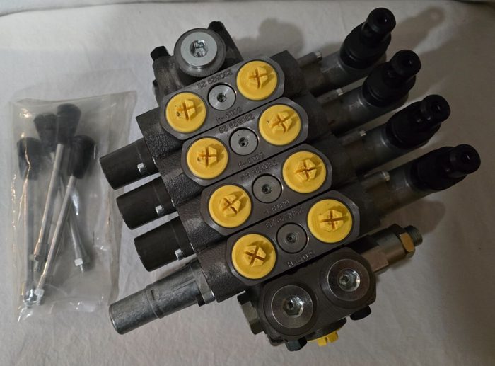
4 Spool Directional Control Valve
Number of Spools: 4
-
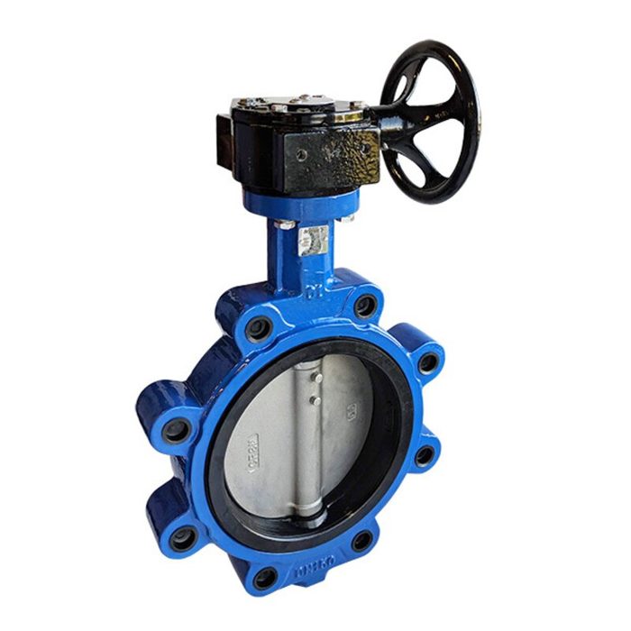
5" Ductile Iron 350 psi Gear Lug Butterfly Valve
Bore: 5"Pressure: 350 psi
-
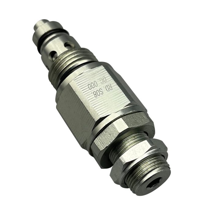
Adjustable Pressure Relief Valve, Direct-Acting
Flow Rate: 20 GPMPort Size: #8 SAE
-
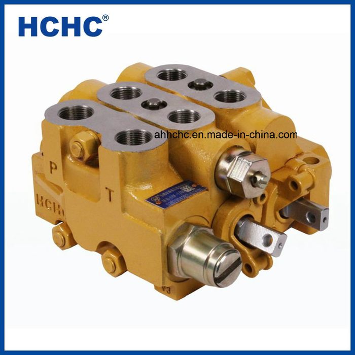
Adjustable Relief Valve
Port Size: 1/2" NPTPressure: 175 PSI
-
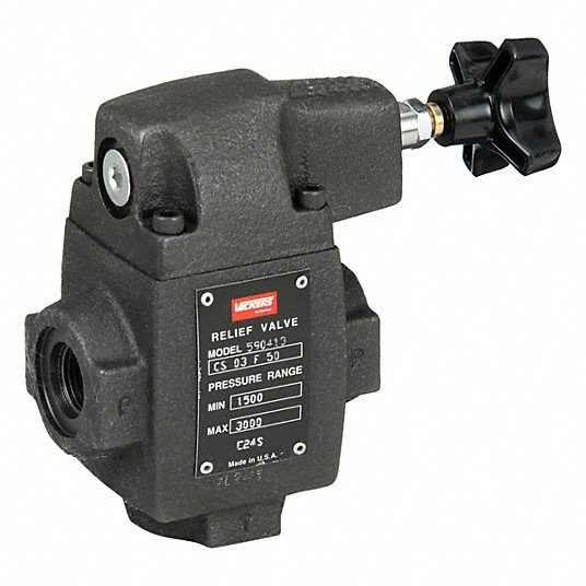
Adjustable Relief Valve, 3000 psi Max Pressure
Max Pressure: 3000 psi
-
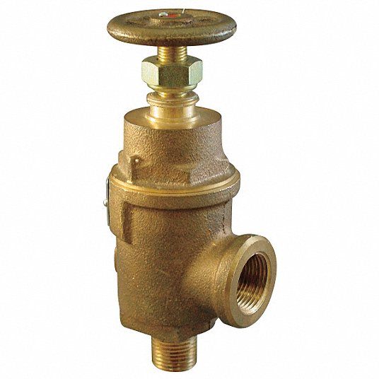
Adjustable Relief Valve, FNPT x MNPT
Port Type: FNPT x MNPT
-
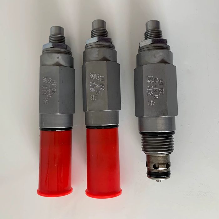
Adjustable Stainless Steel Safety Relief Valve RV10
Pressure Relief Range: 1000-10000 PSI
About hydraulic valves
Hydraulic valves regulate the flow, pressure, and direction of hydraulic fluid within a system, enabling precise control over actuators and other components. Directional control valves (DCVs) route fluid to specific ports, commonly available as spool, poppet, or rotary designs, actuated manually, electrically (solenoid), hydraulically, or pneumatically. Configurations include 2/2, 3/2, 4/2, 4/3, and 5/3 way, with common interfaces like ISO 4401 (CETOP) subplate mounting, threaded port (NPT, BSPP, SAE), or cartridge styles. Pressure relief valves (PRVs) protect systems from overpressure by diverting fluid once a set pressure is exceeded, typically direct-acting or pilot-operated, with adjustable cracking pressures ranging from 10 to 400 bar. Check valves permit flow in one direction only, preventing backflow, and are available as ball, poppet, or swing types, with or without spring assistance. Proportional valves offer continuous, variable control of flow or pressure in response to an electrical input signal, often integrating LVDT feedback for accuracy. Cartridge valves are compact, screw-in components that simplify manifold design and are available in various functions, including directional, pressure, and flow control. Key selection parameters include maximum operating pressure (e.g., 210 bar, 350 bar), nominal flow rate (e.g., 10 LPM, 100 LPM), port size, actuation method, response time, and fluid compatibility. Common materials include cast iron, aluminum, and stainless steel, often with surface treatments like phosphating or zinc plating for corrosion resistance.
How to choose
When selecting hydraulic valves, first define the primary function: directional control, pressure regulation, or flow control. For directional control, determine the required number of ways (e.g., 4/3) and positions, actuation method (e.g., solenoid, pilot), and mounting interface (e.g., ISO 4401, threaded). Next, specify the maximum operating pressure and required flow rate; these parameters dictate valve size and construction. For pressure relief, identify the desired cracking pressure range and whether direct-acting or pilot-operated is suitable for response and stability. For proportional control, define the required resolution, linearity, and electrical interface. Finally, consider fluid compatibility, operating temperature, and any specific environmental requirements for material and seal selection.