Hydraulic Valves
Directional, relief, check, proportional and cartridge valves.
Also searched as: directional valverelief valvecartridge valveproportional valve
About hydraulic valves
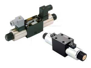
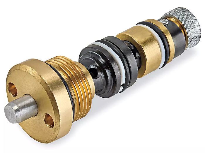
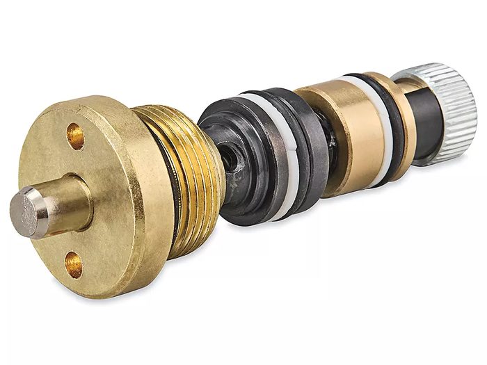
Hydraulic valves regulate the flow, pressure, and direction of hydraulic fluid within a system, enabling precise control over actuators and other components. Directional control valves (DCVs) route fluid to specific ports, commonly available as spool, poppet, or rotary designs, actuated manually, electrically (solenoid), hydraulically, or pneumatically. Configurations include 2/2, 3/2, 4/2, 4/3, and 5/3 way, with common interfaces like ISO 4401 (CETOP) subplate mounting, threaded port (NPT, BSPP, SAE), or cartridge styles. Pressure relief valves (PRVs) protect systems from overpressure by diverting fluid once a set pressure is exceeded, typically direct-acting or pilot-operated, with adjustable cracking pressures ranging from 10 to 400 bar. Check valves permit flow in one direction only, preventing backflow, and are available as ball, poppet, or swing types, with or without spring assistance. Proportional valves offer continuous, variable control of flow or pressure in response to an electrical input signal, often integrating LVDT feedback for accuracy. Cartridge valves are compact, screw-in components that simplify manifold design and are available in various functions, including directional, pressure, and flow control. Key selection parameters include maximum operating pressure (e.g., 210 bar, 350 bar), nominal flow rate (e.g., 10 LPM, 100 LPM), port size, actuation method, response time, and fluid compatibility. Common materials include cast iron, aluminum, and stainless steel, often with surface treatments like phosphating or zinc plating for corrosion resistance.
How to choose
When selecting hydraulic valves, first define the primary function: directional control, pressure regulation, or flow control. For directional control, determine the required number of ways (e.g., 4/3) and positions, actuation method (e.g., solenoid, pilot), and mounting interface (e.g., ISO 4401, threaded). Next, specify the maximum operating pressure and required flow rate; these parameters dictate valve size and construction. For pressure relief, identify the desired cracking pressure range and whether direct-acting or pilot-operated is suitable for response and stability. For proportional control, define the required resolution, linearity, and electrical interface. Finally, consider fluid compatibility, operating temperature, and any specific environmental requirements for material and seal selection.