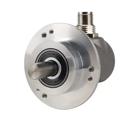
Encoders & Feedback
Incremental, absolute, rotary and linear encoders plus resolvers.
Also searched as: rotary encoderabsolute encoderlinear encoderresolverquadrature
-
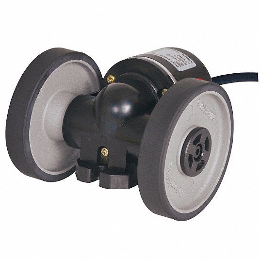
-
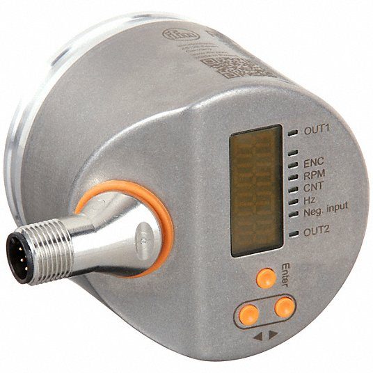
Encoder, Hollow, 10 mm Shaft Dia
Shaft Diameter: 10 mm
-
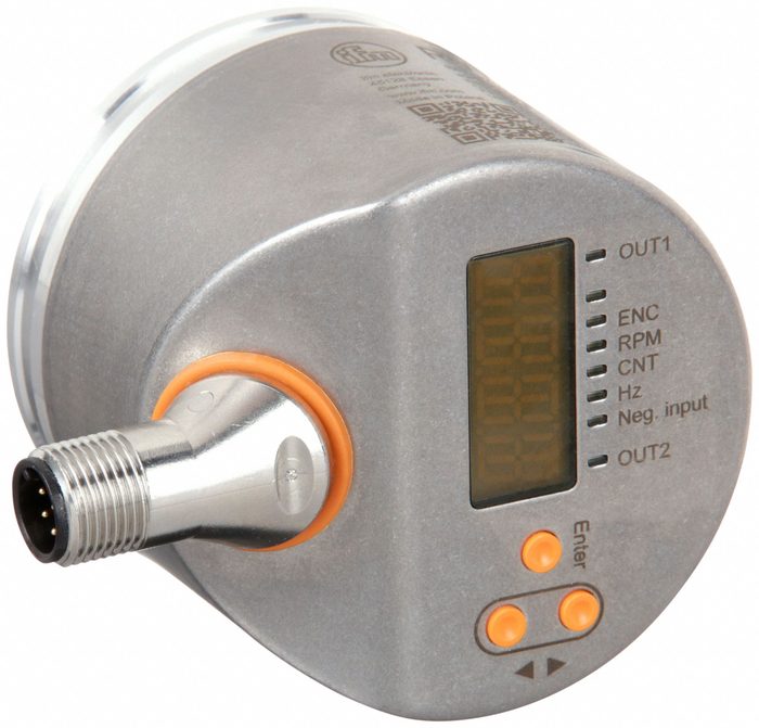
Encoder, Hollow, 6 mm Shaft Dia
Shaft Diameter: 6 mm
-
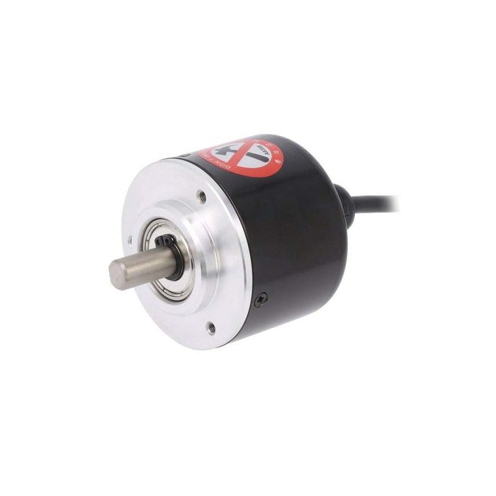
Encoder, Totem Pole, 8 mm Shaft Dia
Graduation: 0.00002-0.00005 inchesMeasuring Force: 2.5 NRange: 0-2.400 inchesStem Diameter: 3/8 inch
-
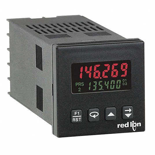
Hour Meter Counter
Mounting: Front PanelSensing: Quadrature
-
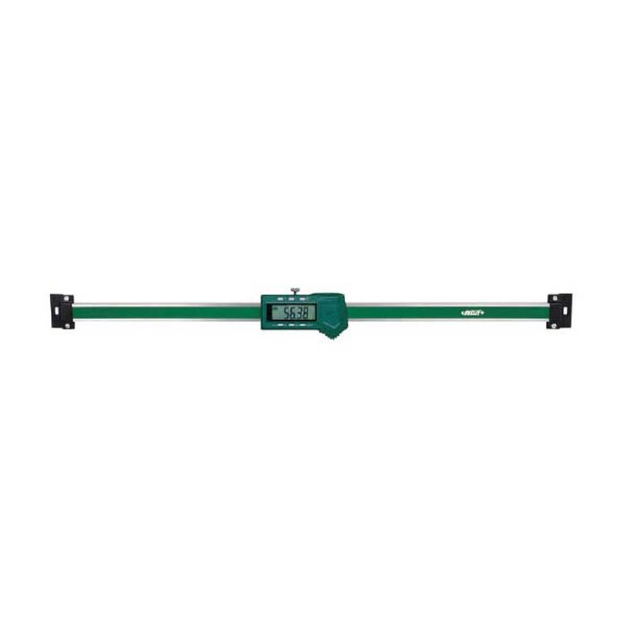
Linear DRO Scale, 0 to 120 in / 0 to 3000 mm
Measurement Range: 0 to 120 in / 0 to 3000 mm
-
Linear DRO Scale, 0 to 28 in / 0 to 700 mm
Measurement Range: 0 to 28 in / 0 to 700 mm
-
Linear DRO Scale, 0 to 76 in / 0 to 1900 mm
Measurement Range: 0 to 76 in / 0 to 1900 mm
-
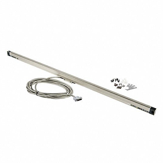
Linear Scale, 0 to 48 in / 1200 mm
Measurement Range: 0 to 48 in / 1200 mmOverall Length: 1398 mm
-
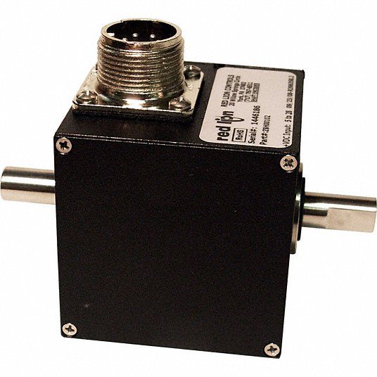
Rotary Encoder, Quadrature, 3/8 in Shaft Dia
Shaft Diameter: 3/8 in
-
Rotary Encoder: Quadrature
Shaft Diameter: 3/8 in
-
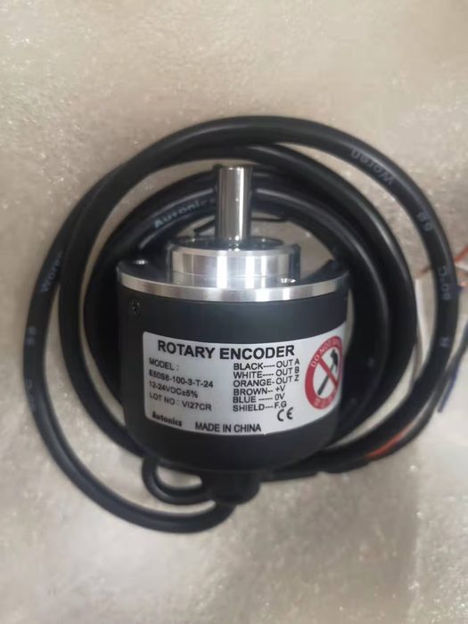
Shaft Encoder
Shaft Diameter: 8 mm
-
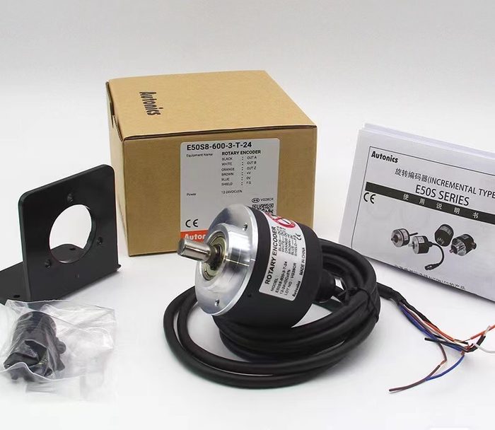
Shaft Encoder Totem Pole 8 mm Shaft Dia
Shaft Diameter: 8 mm
About encoders & feedback
Encoders and feedback devices translate mechanical motion into electrical signals for control and measurement. This category encompasses incremental, absolute, rotary, and linear encoders, alongside resolvers. Incremental encoders output a series of pulses per unit of displacement, often in quadrature (A/B channels) with an index pulse (Z channel), providing relative position. Absolute encoders provide a unique digital code for each position, maintaining position information after power cycling, available in single-turn and multi-turn variants. Rotary encoders measure angular displacement, specified by resolution (PPR for incremental, bits for absolute), shaft diameter (e.g., 6mm, 10mm, 1/4", 3/8"), mounting style (flange, servo, hollow shaft), and output protocol (e.g., HTL, TTL, SSI, BiSS, Ethernet/IP, PROFINET). Linear encoders measure linear displacement, defined by resolution, measuring length, and output. Resolvers are analog inductive devices providing absolute angular position via sine/cosine signals, robust in harsh environments. Key selection parameters include resolution, accuracy, operating temperature range, shock/vibration resistance, IP rating (e.g., IP65, IP67), electrical interface, and supply voltage. Common materials include aluminum or stainless steel housings, with various bearing types for rotary units.
How to choose
When selecting an encoder or feedback device, first determine if relative or absolute positioning is required. For relative, incremental encoders are suitable; for absolute, consider absolute encoders or resolvers. Next, specify the type of motion: rotary or linear. For rotary, define the required resolution (PPR or bits) and shaft interface (solid, hollow, through-hole). For linear, specify the measuring length and resolution. Evaluate environmental conditions: IP rating for dust/moisture, operating temperature, and shock/vibration resistance. Finally, select the appropriate output protocol (e.g., HTL, TTL, SSI, BiSS, Ethernet/IP) and electrical interface for integration with the control system, balancing performance requirements against system complexity and cost implications.