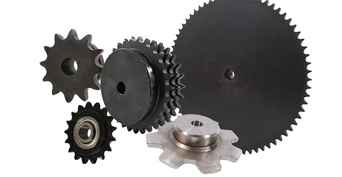
Chain & Sprockets
Roller chain, conveyor chain, sprockets and connecting links.
Also searched as: roller chain#40 chainsprocketsansi chainmaster link
-
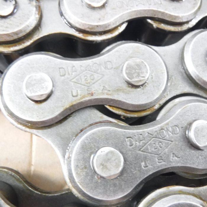
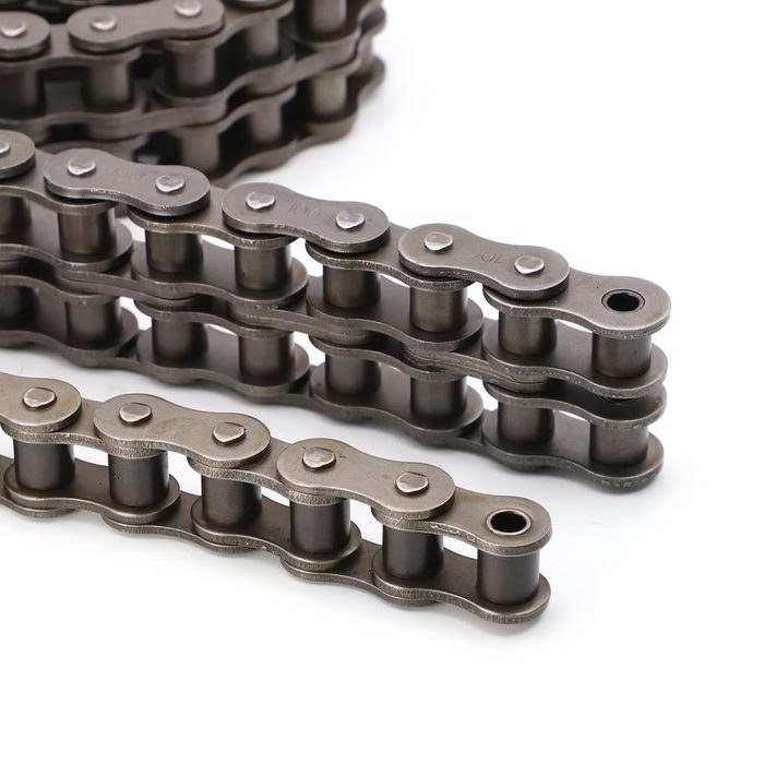
Roller Chain
Length: 10 ftPitch: 5/8 inSeries: StandardSize: 50Strands: 1
-
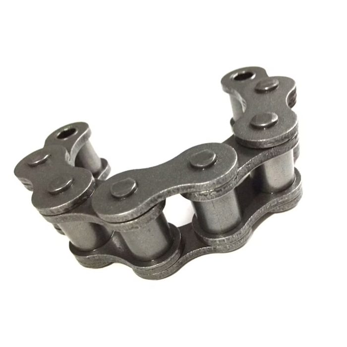
16A-1 Short Pitch Precision Simplex Roller Chains and Bush Chains
Chain Size: 16A-1Pitch: ShortStrands: Simplex
from $1.85Made-in-China $1.85 -
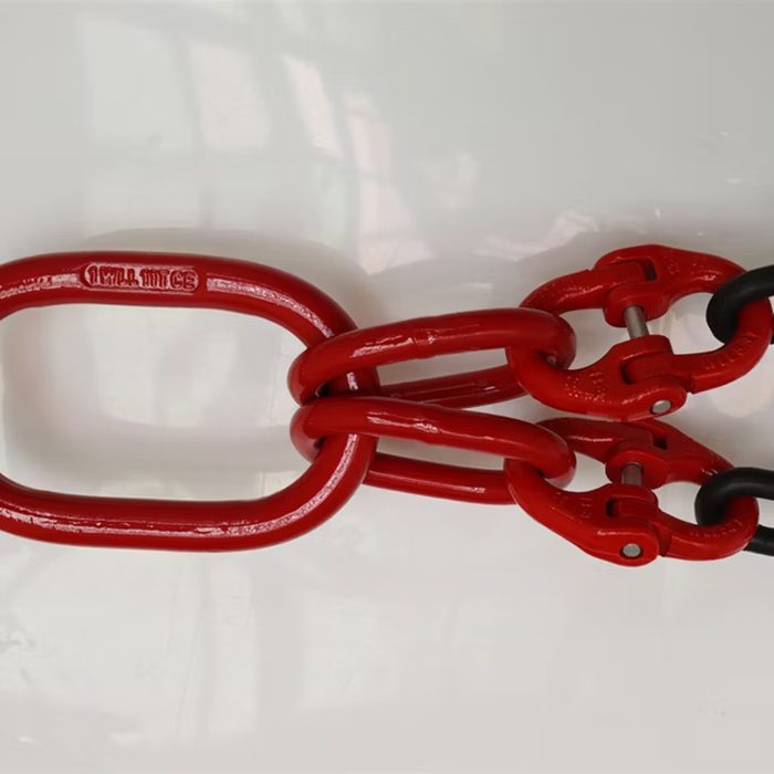
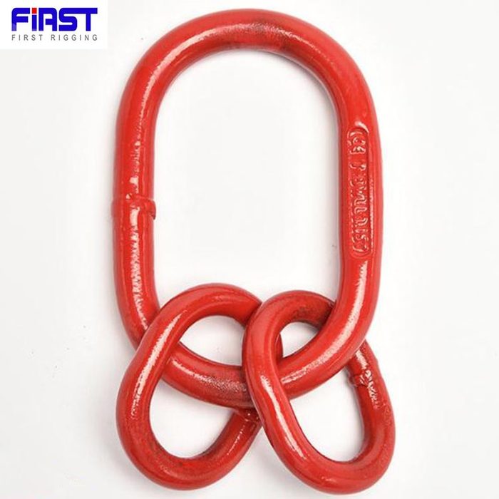
25 Ton Red Master Link Assembly
Color: RedLoad Capacity: 25 TonStrength Grade: 8
-
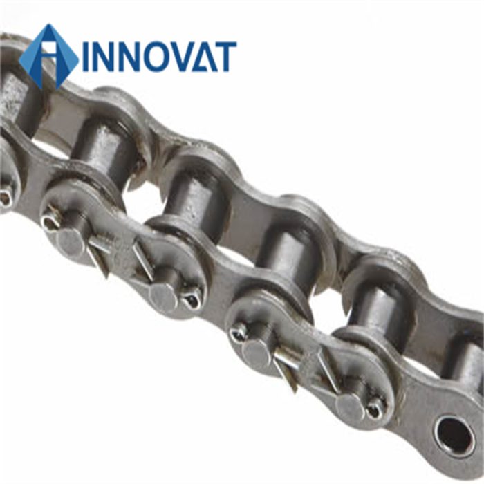
32A-2 160-2 ISO/DIN Industrial Transmission Conveyor Drive Roller Chain Link
Size: 160-2Standard: ISO/DIN
-
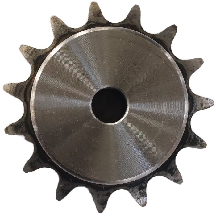
60b Qd Sprockets
Bore Type: QDChain Size: 60b
-
-
-
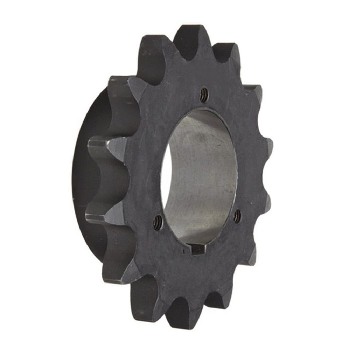
ANSI Standards Double Pitch Sprockets 2040b15 with Stock Bore
Bore: StockPitch: DoubleStandard: ANSI
from $3.68Made-in-China $3.68 -
 from $0.40Made-in-China $0.40
 -
-
-

-
-
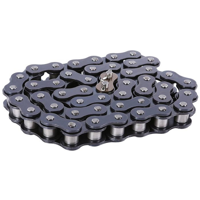
DIN B Series Heavy Duty Roller Chain
Series: BStandard: DIN
from $9.99Made-in-China $9.99 -
-
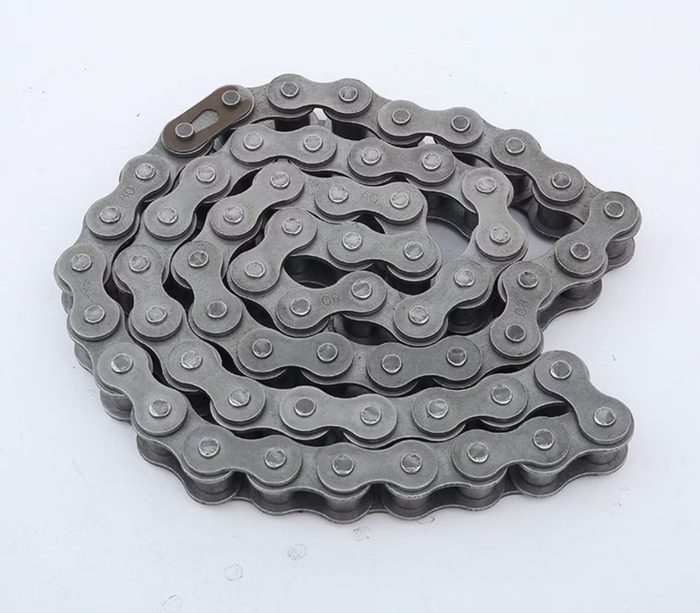
Factory customized 20A 1.2 inch precision roller chain industrial chain drive chain
Chain Size: 20APitch: 1.2 inch
from $3.00Made-in-China $3.00 -
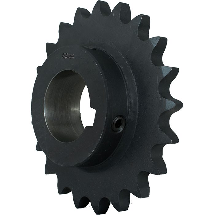
Finished Bore 80BS Sprockets
Chain Size: 80BS
-
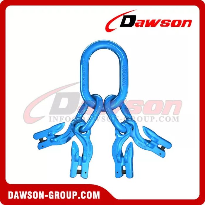
G100 Clevis Grab Hook Assembly with Master Link
Grade: G100
-
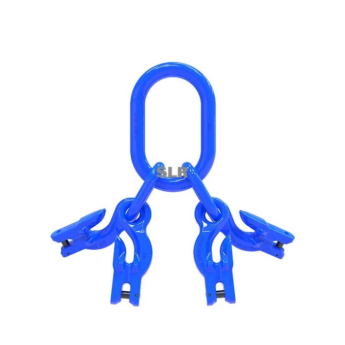
G100 Master Link Assembly with Grab Hook
Grade: G100
-
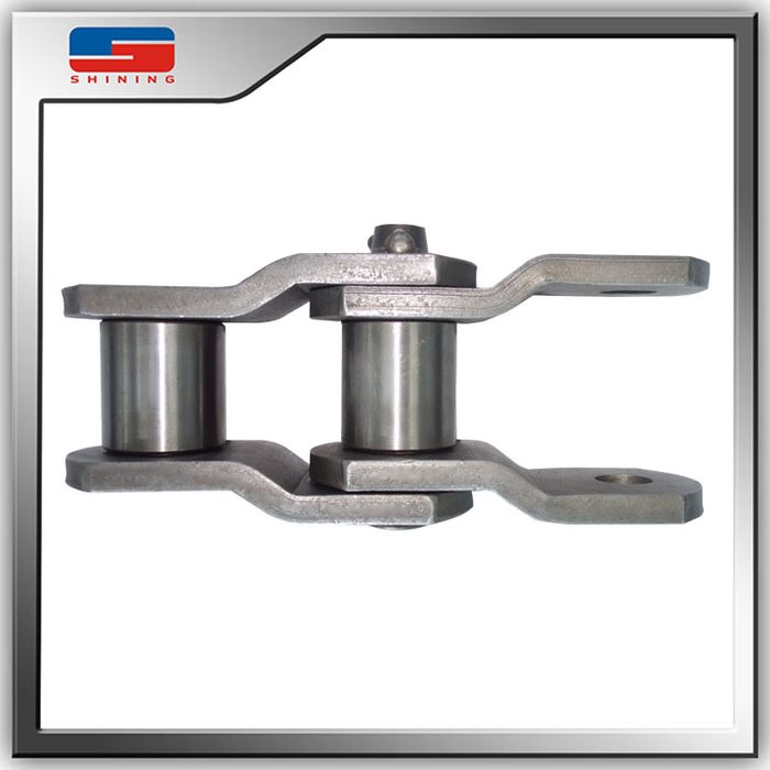
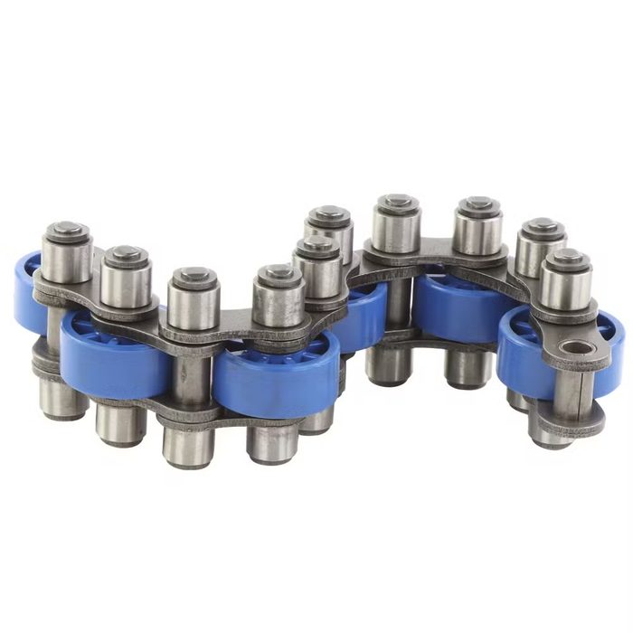
Heavy Duty Stainless Steel Offset Sidebar Roller Chains
Sidebar Type: Offset
from $9.90Made-in-China $9.90 -
-
-
-
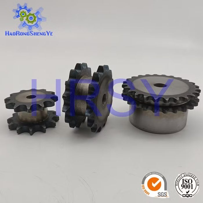
ISO Standard Chain Sprockets
Chain Size: 08b 10b 12bStandard: ISO
-
-
-
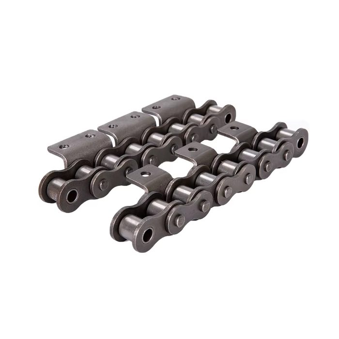
Large Roller Conveyor Chain
Series: A, B
-
 from $18.00Made-in-China $18.00
 -
-
 from $100.00Made-in-China $100.00
 -
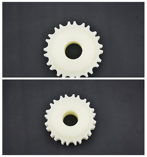
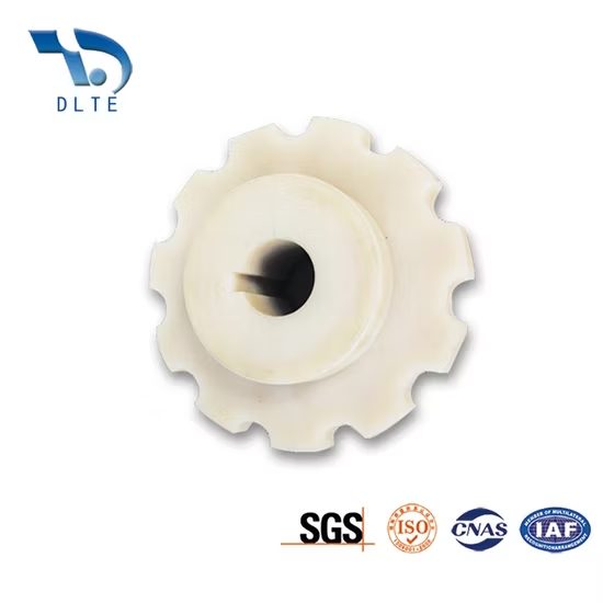
Plastic Conveyor Belt Sprockets Gear
Brand Name: HairiseBusiness Type: ManufacturerCertification: ISO, Ce, FDA, EctChain Size: Width:1.25inchConveyor Part: Nylon Conveyor Chain Sprocket
from $6.00Made-in-China $6.00 -
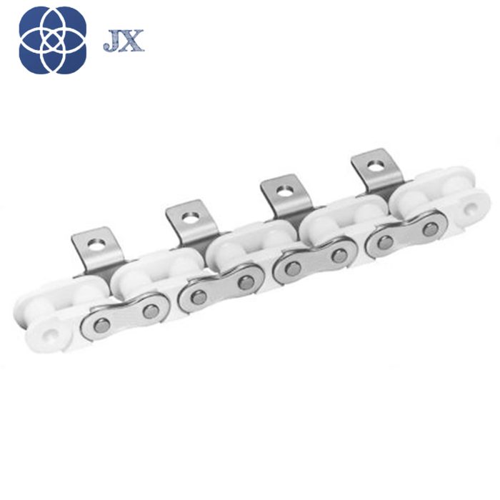
Plastic Roller Chains PC35 PC40 PC50 PC60
Chain Size: PC35 PC40 PC50 PC60
-
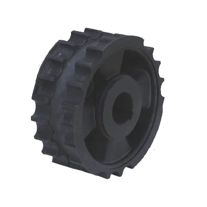
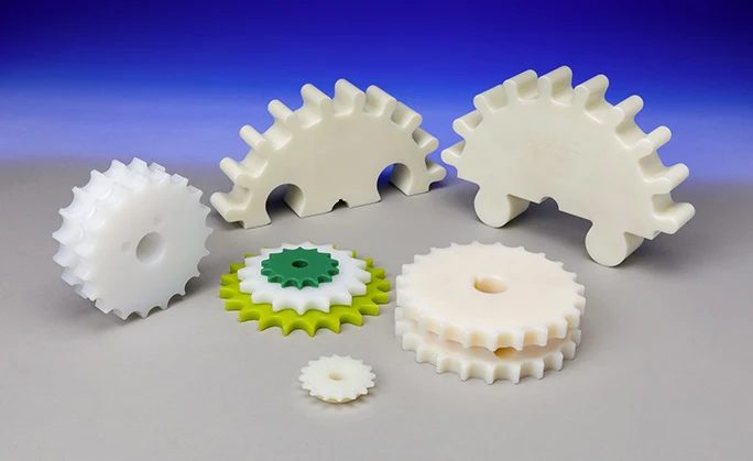
Plastic Split Sprockets for 812-815-881m Chain (Injection)
Chain Compatibility: 812-815-881m
from $1.00Made-in-China $1.00 -
-
 from $48.00Made-in-China $48.00
 -
 from $1.00Made-in-China $1.00
About chain & sprockets
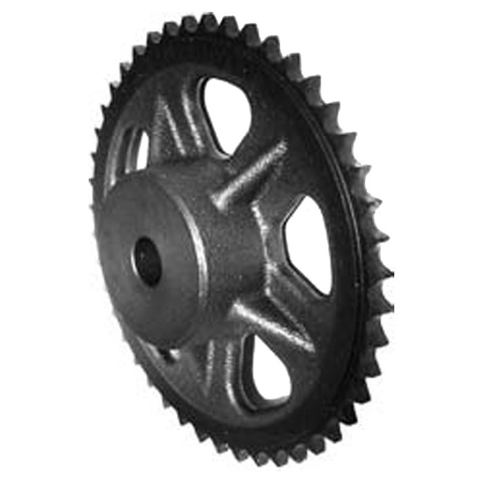
Chain and sprockets transmit mechanical power efficiently through a positive engagement, making them suitable for applications requiring precise timing or high torque transfer. The primary types are roller chain and conveyor chain. Roller chains, standardized by ANSI (e.g., ANSI B29.1) and ISO, consist of alternating inner and outer links with rollers that engage sprocket teeth. Common series include standard single-strand (e.g., #40, #50, #60), multi-strand for higher power, and heavy series for increased fatigue resistance. Conveyor chains are designed for material handling, often featuring larger pitches, specialized attachments, and sometimes hollow pins for custom fixtures. Sprockets are toothed wheels that mesh with the chain; key selection parameters include pitch diameter, number of teeth, and bore configuration (e.g., plain bore, finished bore with keyway and setscrew, Taper-Lock). Connecting links (master links) are used to join chain ends, available in spring clip or cottered styles. Critical dimensions for chain include pitch, roller diameter, and width between inner plates. Sprocket dimensions include pitch, number of teeth, and hub diameter. Materials typically range from carbon steel (e.g., 1045, 4140) for general use, to stainless steel (e.g., 304, 316) for corrosive environments, and sometimes nickel-plated or zinc-plated steel for enhanced corrosion resistance.
How to choose
Selecting the correct chain and sprocket system involves a sequential decision process. First, determine the required power transmission capacity and operating speed to establish the chain pitch and number of strands. What is the driven load and prime mover RPM? Second, consider the application environment. Are corrosive agents present, or is washdown required? This dictates material (e.g., carbon steel, stainless steel) and plating. Third, define the center distance and desired speed ratio to calculate the number of teeth for both driver and driven sprockets. Fourth, specify the sprocket bore type and diameter based on the shaft interface (e.g., plain bore, finished bore with keyway, Taper-Lock bushing). Finally, select the appropriate connecting link type (e.g., spring clip, cottered) based on ease of assembly and security requirements.